Information on current publications with open paper submissions.
GET INVOLVED
Discover the many ways to support IEEE Photonics as a volunteer.
FIND A CONFERENCE
Information on upcoming conferences for the Photonics field.
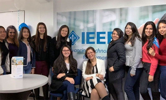
Nominations for the 2024 Women in Photonics Excellence Award
March 15, 2024
READ MORE
IEEE's Celebrates 140th Anniversary in 2024
February 9, 2024
READ MORE
OFC 2024 - Register Now
November 21, 2023
READ MORE
IEEE Congratulates Nobel Prize Winners: Open Access Articles Available
October 20, 2023
READ MORE
Announcements for Recipients and Submission Deadlines for Upcoming Awards
Our awards program has been established to recognize outstanding achievements and for those accomplishments which enhance the quality of life for all people throughout the world.
IEEE Photonics Society is a volunteer-driven organization.
We’re made up of researchers, academics, students, and industry professionals who are dedicated to transforming breakthroughs in photonics to revolutionize our daily lives. From our conferences and publications to networking opportunities, chapters, and awards—this is a community with a purpose and sense of belonging.